All this time I wasn't sure what I wanted to do for artwork. I had originally planned to print off some artwork from a real cab, but as the project went on I felt like I wanted this to be more my own custom creation, in every respect. Again, this project is about nostalgia. When I was a child we used to go for beach holidays at a place called Currumbin, which is on the Gold Coast in Queensland, just south of Surfer's Paradise. This was and still is a beautiful place, though development is slowly making it less quaint. We used to get a house right on the the beach and walk down the shops for ice cream and there were a few arcade machines around. These are some of the happiest memories I have, so I wanted a theme that embodied that feeling. So I decided to call the cab "Paradise Arcade" and went with this sunset theme. In some ways, this embodies not just that specific memory, but how I feel about the 80s in general.
This is what I came up with, which I put together in inkscape. I was really happy with the end result. It took me a while, especially since I drew it all using my laptop trackpad (argh!), but I'm glad I put the time in. I sent hi res versions off to a guy who builds arcade machines and prints artwork for people who I found on the Aussie Arcade forums. Originally I was just going to do the marquee, and cover the control panel with textured black vinyl, but again, when you come this far, you want to go that extra mile, so I did control panel artwork as well.
The marquee:
The control panel:

While I waited for that to arrive, I had to figure out what to do about a bezel. I mentioned in an earlier post that there were some details I hadn't full figured out when I made the plans for this cab, some of that was no problem, but some of it was. And the major problem was that I hadn't fully decided on what monitor I was going to use when I started building, and I didn't yet have a solution for a bezel and glass/perspex. These were things I figured I could sort out later. The problem is, I didn't mount the monitor deep enough into the cab, and that didn't leave me with much space to work with. One reason this happened is that it's not easy to measure the dimensions of a CRT tube, especially a large one, because it has a curved front. I underestimated the depth of it a bit. leaving very little space between the front of the tube and where the glass would go. Also, because I used such a large monitor in a narrow cab, there was very little space between the edges of the monitor and the sides of the cab. This second issue is what meant it would be impossible to find an actual arcade CRT monitor bezel that fit. Actually finding bezels in general is very difficult. They were thin plastic that got damaged easily, and of course no one makes them any more. I actually have three that I've picked up from various places, but none of them fit.
So my solution was to make a bezel. I knew it was possible, I'd seen others do it. I started by just taking a few measurements, cutting one out of cardboard and slotting it in. Wow, to my amazement it actually looked decent!

As good as this looked at a glance, it wasn't a proper solution. The cardboard was too thin and flimsy, and it looked like cardboard. But it demonstrated that it was definitely doable.
Meanwhile the artwork arrived. I installed the marquee, which is adhered to one piece of acrylic with another piece on top. Real marquees were often painted onto the back of perspex, so this mimics the look. It's held in place with some aluminium angle that is painted in satin black and screwed into the cab. Very happy with how it looks.
Next came the control panel artwork. This was tricky to apply, but I totally nailed it, lined up perfectly with all the buttons and no bubbles underneath.
Looks great with the buttons installed!
There it is, artwork installed! The cab is now very close to being complete cosmetically! You can also see in some of these photos that I have installed the speaker grills. I couldn't find perforated metal sheet, so I bought some speaker grills for big sub woofers, cut squares out of the middle, bent the edges so they had a bit of a bevel around the perimeter, spray painted them black, and screwed them into place.

With that done, I returned to the bezel. One difficulty here was getting measurements. I was going to stick with my idea of cutting the bezel out of cardboard, but transcribing the curve of the monitor perfectly onto anything, was not easy. 3D modelling came in handy here. I figured out where I wanted the outer edge of the bezel to sit, basically a rectangle that rests against the inside edges of the cab, leaving a few millimetres for a piece of glass to sit in front. Then I measured the straight line distance between a few points along those lines to a few points on the tube, around the display area - basically where the bezel would actually frame the screen. With that plus a little trigonometry, I was able to put in the basic coordinates of the bezel into my SketchUp model. Then, I could use a best fit curve to connect all the points, which I assumed would be a close enough approximation of the curve of the tube.

Now it was much easier to take measurements from this, and make the pieces of the bezel. In general it can be a really useful approach to make a 3D model of something, and then take measurements from that. As long as you have some dimensions, the computer can calculate the rest, and then you can easily measure any dimensions you want virtually. I use this approach a lot when I need to fabricate something with complex dimensions.
I built the bezel out of the same cardboard, then put it in place to see if it fit. Then I reinforced the structure with poster board, and then covered the surface with a textured black adhesive vinyl from DC-fix. This vinyl is amazing, it'll stick to anything, and it's thick and textured like plastic.
The end result looked just like a moulded plastic bezel. I was very happy with this.

I put it in place with some pins going through the structure at the back and securing it to the inside of the cab. But it was a pretty snug fit anyway. Then I put the perspex in. This was where my lack of planning really bit me in the arse. There was just no easy way to mount this, I simply didn't have the room to mount brackets or anything. At least not at the top. Down the bottom I did, there's plenty of room behind the control panel, but up the top the speaker boxes protrude into the same plane where the perspex would go, so I had to screw the top of the perspex into the back edge of the speaker panel. This was really difficult, because the monitor obstructs access to this part, and so I can't easily remove and replace this, and it's only secured at the top and bottom with nothing at the sides. It simply rests on the bezel along the sides, which is sandwiched tight between it and the monitor. I'm not happy about this. There was nothing else I could do, at this point, but it should have been better planned. It should be easy to install and remove and it should be very secure. But it is what it is. Next time I will know better. Also it was now that I realised I had messed up when I originally cut out my side panels. But in general, cosmetically it looks fine! But the perspex is more fragile than it would be on a real arcade machine, and that bothers me, because the rest of this thing is bullet proof. Also, I didn't use acrylic, I used clear PVC, because it could get it off the shelf at the hardware store, where as buying good quality acrylic off the shelf is pretty much impossible. The PVC is not good, it has poor visual clarity. There are faint vertical lines in it that bend the light. Mostly you can't notice it, but sometimes you can. It's also softer than acrylic, so the sheet is less rigid. I will replace this with good acrylic one day.

That said, the cab was now cosmetically complete. And I have to say, I am impressed with what I was able to accomplish. I never fully expected to create something that looked this good, and this authentic, and I never get tired of seeing it there sitting in my living room - though actually I have now moved interstate and it's sitting in storage :(


The cab sat like this for some time before I got round to making it functional. First I wanted some convenient interfaces on the back. So I made this panel with an Ethernet port, a USB port, a headphone port and an AUX port. The main point of the Ethernet port and the USB port are to allow me to connect to the computer inside remotely to configure the software, and to easily add files. This is much better than trying to operate a computer with a low res arcade monitor. The headphones port allows it to be played late at night or in some other context where one doesn't want to disturb others but still wants sound. The AUX port allows you to hook up some external sound source, and when you do it overrides the audio being fed to the speakers. With everything being on smart phones these days, it removes the need for an additional sound system in the living room.

Below the panel I installed a normal arcade button, which is wired up to the PC as a power button. So just reach back here when you want to turn it on.
I also installed a button on the top, out of site. This is the "shift" button. When pressed, it changes the function of the controls to alternative functions in Mame. For example, hold the shift button and press up and down on the stick to change the volume, or press a button to exit game, or add credits. This is a nice function than the IPAC keyboard encoder has, and removes the need for extra buttons on the control panel that would make the machine look less authentic.

Here is the PC sitting inside the machine. I didn't see any need to de-case it. Much easier to leave in in it's case so that the whole thing can be removed if necessary for upgrades, repairs, etc. The PC is plugged into a slave/master power board. The way these power boards work is when the item plugged into the "master" port is turned on, it activates power to all the "slave" ports. So when the PC is turned on via the button on the back of the cabinet, the power is also turned on to the monitor, the marquee light, and the amp. When the PC is shut down, power is cut to all those things. The cord to the power board is cut off and wired into a junction box, and from that box a power cord goes out the back of the cab. I basically did that because I wanted a black cord, and could only find a white power board. I did put a plastic bushing around where the power cord exits the cab so that it looked like a power power cord, not just an extension lead coming out of a hole.

I hooked the chassis up to the tube. You can see that a wood panel separates the cavity behind them monitor from the cavity below where the PC and other components are. This is for safety, and it gives a surface to mount the chassis on. I ordered the chassis from a guy here in Australia who can customise a chassis to turn just about any reasonably common TV tube into an arcade monitor. To say that this guy is a valuable member of the local arcade enthusiast community is an understatement. He makes the acquisition and repair of arcade monitors very easy. I wish I had his knowledge and skills. I won't give out his details because he only serves Australian customers and doesn't want to be bombarded with international requests. The computer has an ArcadeVGA card from Ultimarc that allows the computer to spit out arcade video modes. Paired with GrooveyMame, you get arcade perfect graphics in the vast majority of games. To say that it looks incredible is an understatement.
You can also see here the handles installed. Many arcade parts shops sell these, the cavity has a gap above for your fingers, and a grill below to serve as a vent.
This panel lifts completely out as you can see in the above images, and locks in place with a key. Again, important for safety to keep this locked up.
The perfect keyring, bought at Funspot with redemption tickets :)
The first iteration of the GUI. Nice and simple. I used MALA as a front end. It's no longer in development, but it's good for low res setups. I'm running the front end at 320x240.
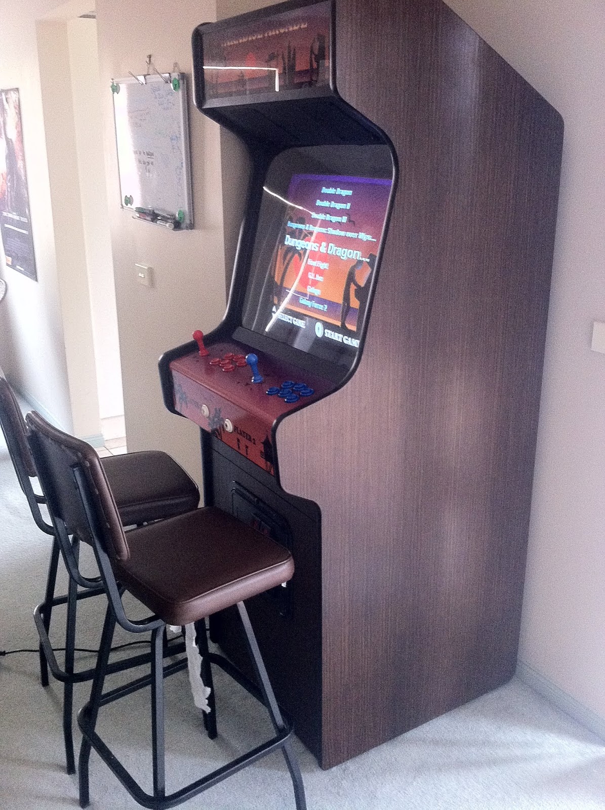
Ready to play, with a couple of old lab stools they were giving away at the university when they were renovating the old teaching labs.
Ahh, the glow of those buttons makes me so happy. I didn't use incandescents, I used red led bulbs that fit in the same sockets. It might not have quite the glow of incandescent bulbs, but it's close enough. They are wired into the PC's power supply.
The very last thing I did was install the marquee light. There's not a lot of space behind the marquee thanks to my speaker boxes, but I just put a piece of black poster board in there and stuck a single strip of warm white 3528 smd leds to it. It plugs directly via an adaptor into the power board and has a dimmer switch on the cord. You can also see here I have updated the GUI. It now displays the marquee of the game selected, along with a screenshot. Anything more than that would be too much on such a low resolution screen.
Also here you can see a yellow cup sitting on top of the cab. That cup is full of tokens. I bought 250 assorted tokens off ebay, all the same size of course, but from different arcades and amusement parks, and I got coin mechanisms for the same size parts. So yes, you do need to put coins in to add credits :)
I'm really happy I did this, it's actually really cool to look at the tokens and all the different old arcades.
Ahhh, that nice glow. Sometimes at night I just turn on the marquee light when I want some dim light in the room :)
And that's it, the project is complete. The only other work I did on it after this was to add a coin box, which I built out of plywood. This was actually kind of interesting because I installed it and then realised you needed a lot of tokens in the box before it gave that nice sound "chink" sound of coins falling on other coins. So I had to build sloped sides into it tapering to a narrow base so that the coins would begin to pile into each other after just a few had been added.
Overall, I'm extremely happy with it how this turned out. It looks great, it looks authentic, it actually exceeded my expectations in every regard. I think I learnt from this project that really I can build anything, all I need is time and diligence. Even if it seems daunting, every project breaks down into a series of steps. If you just do one step after the other, and do each one with care and attention to details, in the end you will have an amazing finished product. This was actually a valuable lesson for life, as corny as that sounds.
So, what am I happy about:
- Looks authentic! This really does look like the real thing, and I think it can easily pass as a genuine retro cab from the 80s or 90s. That was really important to me.
- Fake wood grain looks awesome. I would like to cover all the walls of my house with it.
- The CRT monitor is amazing! The image looks so good, it feels me with such a sense of nostalgia to have that right in my face.
- The controls great, authentic MCA sticks, just how I remember
- Having actual tokens and coin mechs really completes the experience. I recommend everyone do this with their cabs, you won't regret it.
What am I not so happy about:
- honestly, the monitor is a little TOO big. It's so large, and so close to your face. I think in hindsight a 25 inch monitor would have been the better choice. When you are so close to such a large screen, the imagine quality suffers a little. They just weren't designed to be viewed from so close. The phosphors, and the gaps between scan lines, seem far more obvious. But then, on other days, I am very happy with the decision.
- As mentioned further up the page, I'm not happy with the clear PVC over the screen. It needs to be replaced with acrylic. It just doesn't have enough clarity. Mostly it's not noticeable, so I haven't bothered replacing it yet. Part of that is probably because of how difficult it was to install, and will be to remove. Which leads me to my next point.
- I should have planned the construction better. Easy to say in hindsight, you obviously learn a lot when you build your first cab. But the result is a bezel and perspex that is not easy to remove, and not as securely mounted as it should be.
- I mentioned in the previous post that I actually made an error when I cut out my side panels. The distance between the control panel and the speaker panel should be a bit larger by a couple of centimetres. It's a small thing, but the space in which the monitor sits should be a bit taller, and as a result the cab looks a little bit squished. It's not something anyone else would likely think looking at it, but I spent a very long time adjusting the dimensions of the model so that it looked just right. And even a centimetre here or there, wider, narrower, taller or shorter, makes a difference to my eye. Just a careless error that I didn't even notice until I was making the bezel and trying to figure out why what I was doing on the computer wasn't matching what was happening in the real world. This is why the bezel disappears down behind the control panel more than it should.
- Because the control panel areas is actually many different surfaces - the steel panel, the wood on either side, the wood that makes the curved front edge, the wood panel at the front - beneath the vinyl you can see and feel seems and joins. I should have put more effort into making this a flawlessly smooth surface by adding filler and sanding it, or something. You don't really notice it, but it's annoying. Really having an entirely metal control panel bent into shape, would have been better, but my friend who made the steel panel for me said he couldn't do it.
These things are minor, but I am a perfectionist. But my displeasure is dwarfed by my pleasure. I dreamt about having a cab ever since I was a small child, and now I have one. It's pretty special, and was worth every effort and expense I put into it.
All up this cost me about $2,500 AUD to build. But a lot of that cost was extra materials I experimented with but didn't use, or paint jobs that I had to redo, or panels I cut, but then discarded because I changed my mind about something. I learnt a lot when doing this project, and next time I would do it better and cheaper. And there will be a next time, I have started designing another cab, which I will make a separate post about.
If you have any questions or comments, feel free to put them in the comments. There are a lot of details I didn't cover in this blog, as such it doesn't serve as a very good guide for anyone looking to build their own. But I'm happy to try and help anyone who is :) Hope you enjoyed reading about my project!